
NodeMCU pinout
For practical purposes ESP8266 NodeMCU V2 and V3 boards present identical pinouts. For our mechatronics projects we are mainly interested in the following pins:
Power pins (3.3 V).
Ground pins (GND).
Analog pins (A0).
Digital pins (D0 – D8, SD2, SD3, RX and TX – GPIO XX)
Most ESP8266 NodeMCU boards have one input voltage pin (Vin), three power pins (3.3v), four ground pins (GND), one analog pin (A0) and several digital pins (GPIO XX).
ESP8266 NodeMCU schematic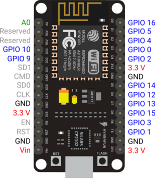
If we want to interact with a digital pin in Arduino IDE we have to remember the GPIO number (0..16), whereas for the analog pin the alias is used (A0). Digital pins can be used as inputs or outputs, however the analog pin can only be used as an input.
| PIN | Code | Arduino Alias | PIN | Code | Arduino Alias |
| A0 | A0 | A0 | D6 | GPIO 12 | 12 |
| DO | GPIO 16 | 16 | D7 | GPIO 13 | 13 |
| D1 | GPIO 15 | 5 | D8 | GPIO 15 | 15 |
| D2 | GPIO 4 | 4 | SD2 | GPIO 9 | 9 |
| D3 | GPIO 0 | 0 | SD3 | GPIO 10 | 10 |
| D4 | GPIO 2 | 2 | RX | GPIO 3 | 3 |
| D5 | GPIO 14 | 14 | TX | GPIO 1 | 1 |
For example, the following code initializes the GPIO 4 and 5 digital pins as input and output, respectively and the analog pin (A0) as input.
pinMode(4,INPUT)
pinMode(5,OUTPUT)
pinMode(A0,INPUT)
Read Breadboard, Pinout and Dimmable LED with Pulse-Width Modulation (PWM), to know more about how to interact with pins in Arduino IDE, particularly the ESP8266 NodeMCU pinout section.